New Customer?
Create your accountNo products
Prices are tax included
DIY Tutorial - Wiring a Toroidal Transformer
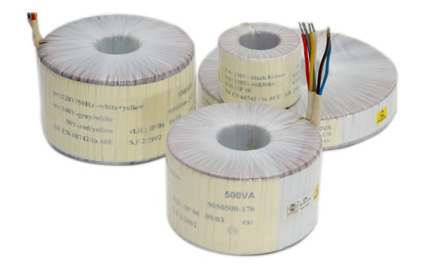
Toroidal transformers and their wiring
Following a number of requests concerning the connection of toroidal transformers to our modules, here are some schematics and photos illustrating the correct way to wire them.
This tutorial is intended only as a guide, and Audiophonics accepts no responsibility for any problems that may arise during wiring. Perform all operations WITHOUT VOLTAGE.
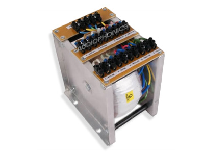
First, of course, you'll need a toroidal transformer, custom-made or otherwise, which you can find in our dedicated section: Toroidal transformers.
The principle applies to all AC-powered modules.
Non-exhaustive list:
- DAC 1955 MK3
- Audiophonics DAC1796
- Audiophonics PGAVOL
- Audiophonics Preamplifier module
- Audiophonics XLR/RCA
- Audio symmetrizer desymmetrizer
- A-13 2x15V 1A regulated power supply module
- LITE DAC-AE Digital-to-analog converter
Cable colors are subject to permanent variation, depending on the toric used.
Introduction to wiring toroidal transformers
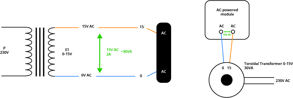
Wiring a toroidal transformer with a single primary winding to 1 secondary winding
This is one of the most basic forms of toroidal transformer. Simply connect the two cables to the power input of your module, accepting the voltage delivered by the secondary winding of your toroidal transformer.
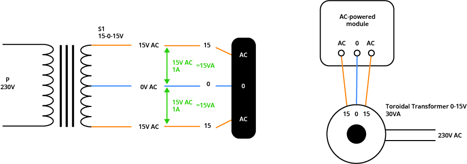
Wiring a toroidal transformer with a single primary winding to 1 three-wire secondary (midpoint)
There are also three-wire secondary windings. These feature a midpoint and are ideal for modules with AC-0-AC power supply connectors.
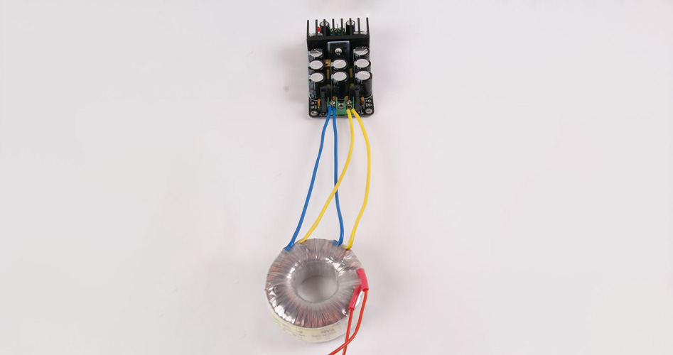
Wiring double-wound toroidal transformers
Wiring a toroidal transformer with a single primary winding to 2 isolated secondaries
This is the simplest way to connect a toroid with 2 secondary windings. This is valid for modules that accept the voltage of the toroidal transformers in question and have AC-0 / AC-0 connectors. However, with a toroidal transformers having several secondary windings, it's also possible to create a mid-point, to connect them in parallel or in series.

Wiring a toroidal transformer with a single primary winding to 2 secondaries by creating a midpoint
In this case, we have a single primary (P) receiving a mains voltage of 230V and two secondary windings (S1 and S2) that we can wire by creating a midpoint. For example, for a 2x(0-15V) toroid, the two secondary windings each deliver voltages of 15V AC per winding. To create a reference point, simply connect one of the two cables of each secondary winding whose voltages are in phase opposition. This will create the “artificial 0”.


Wiring a toroidal transformer with a single primary winding to 2 secondaries connected in parallel
The two secondary windings can also be connected in parallel, to maintain the voltage of a single winding while doubling the current capacity.

Wiring a toroidal transformer with a single primary winding to 2 secondaries connected in series
Series wiring allows the voltages of two windings to be added together, while maintaining current capacity.Series wiring allows the voltages of two windings to be added together, while maintaining current capacity.

Dual-voltage toroidal transformers
Example of a 2x15V + 1x9V toroidal transformer
This toroidal transformer has 3 secondary windings, including two 0-24V AC and one 0-9V AC. You can therefore make all the connections described above with the two windings of the same voltage, but also supply an additional module or part of a module with 9V AC.

Example of a 15-0-15V + 1x9V toroidal transformer
This toroidal transformer has 2 secondary windings, one 15-0-15V AC and one 0-9V AC. You can therefore supply one module with an AC-0-AC input and another with a 0-AC input.

The case of mains voltages
Connect two 115V AC primary windings to 230V AC.
Simply wire in series.

Connect 2 primary windings 115V AC to 115V AC
Simply wire in parallel.

As a reminder, a toroidal transformer is a component that needs to be completely isolated from ground.
The special case of toroidal transformers with shielding
Example of a shielded toroidal transformer
This type of custom-built toroidal transformer features a green/yellow cable connected to earth, enabling the installation of a shielding screen. This cable is not connected to the transformer coil, but to a metal plate. It is usually grounded via the device housing, for example. There are two types of shielding:
- Electromagnetic shielding: protects external components from any electromagnetic waves emitted by the transformer.
- Electrostatic shielding: protects the transformer's internal coil from the electrostatic waves it emits.
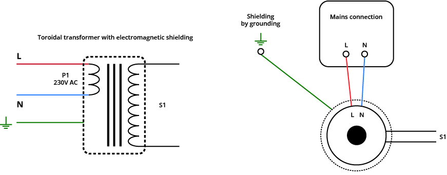
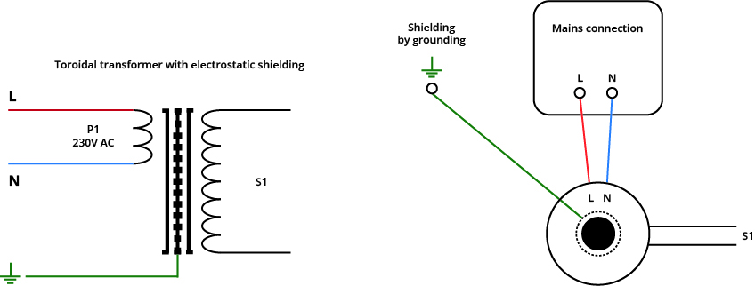
The special case of toroidal transformers with thermal fuses
Example of a toroidal transformer with thermal fuse
This type of toroidal transformer is made to custom specifications. Either the manufacturer directly wires the fuse internally in the transformer, or he leaves the cables visible, allowing the thermal fuse to be used. In this case, it's up to the user to wire the fuse correctly. To wire your thermally fused toroidal transformer properly, simply make a series connection, ensuring that the fuse is on the phase side to avoid any persistent current. 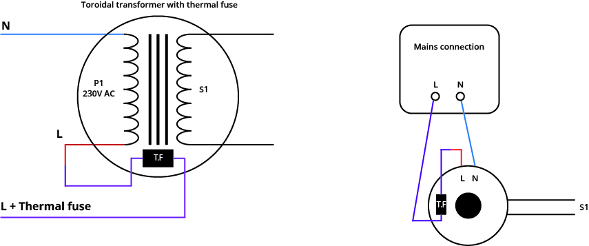
Locate your windings to phase the primary and secondary windings
The winding identification convention
There is a phasing convention for toroidal transformers, represented by a dot on the diagrams. This is used to phase the primary and secondary windings. At Audiophonics, toroidal transformers are designed so that the windings start counter-clockwise. Below you'll find the correspondence between the electrical diagram and the physical representation of a toroidal transformer. Use the indications on the toroidal transformer as a guide.
Discover our catalog of toroidal transformers
If you have any questions, please feel free to ask us in the comments or via the contact form. We'll get back to you as soon as possible.
Rechercher dans le blog
Blog categories
Latest Comments
Audiophonics Team
on DIY Tutorial - PiCorePlayer - Installing...Pierre Bommel
on Lecteur réseau Opensource : SolutionsPierre Bommel
on DIY Tutorial - PiCorePlayer - Installing...Audiophonics Team
on Tutorial DIY - Power cable ELECAUDIO CS-331B



3 Commentaires
Laisser un commentairePierre Roy 2019-02-01
Claudio Menichelli 2023-12-07
The documentation you sent me refers to a Toroidal transformer with the possibility of connecting the 2 outputs in parallel. Ok I knew this that it was possible for Toroidal Transformers
I instead asked if it was possible to connect the 2 outputs in parallel of an R-Core transformer
Thank you
Audiophonics Team 2023-12-08