New Customer?
Create your accountNo products
Prices are tax included
Understanding the different power tubes and their abbreviations

Vacuum tube
From how they work to data sheets
The different types of power tube, also known as lamps, result from the gradual addition of components to modify their behaviour. We'll start by looking at the most common types of tube and how they work.
The basic principle: The Diode
To understand how an power tube works, we first need to explain the mechanics at work in a vacuum diode, often used as a rectifier.
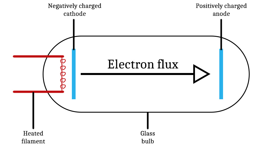
The principle is simple: two electrodes are placed on either side of a vacuum tube, one positively charged, the other negatively charged. Then, using a filament that works in a similar way to an incandescent lamp, the negatively charged electrode is heated. This action will strip electrons from the latter, which will be propelled towards the positively charged electrode. The heat produced by the filament will create a current between the two electrodes. In a tube, the electron-emitting electrode is called the cathode and the electron-receiving electrode the anode.

The most simple power tube: The Triode
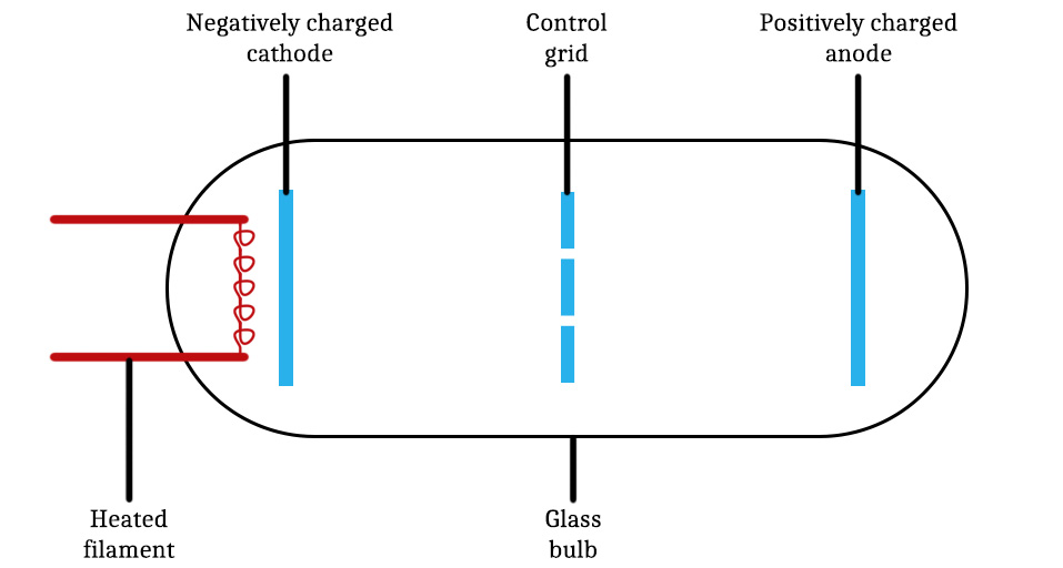
To this fundamental operation, the triode adds a control grid, also powered, between the cathode and the anode. By varying the grid voltage in relation to the cathode voltage, it is possible to absorb some of the electrons emitted by the cathode, creating a variable current between the anode and cathode. This variation in current is then converted into a variation in voltage and so in power: the signal is amplified.

Making the triode more reliable: The Tetrode
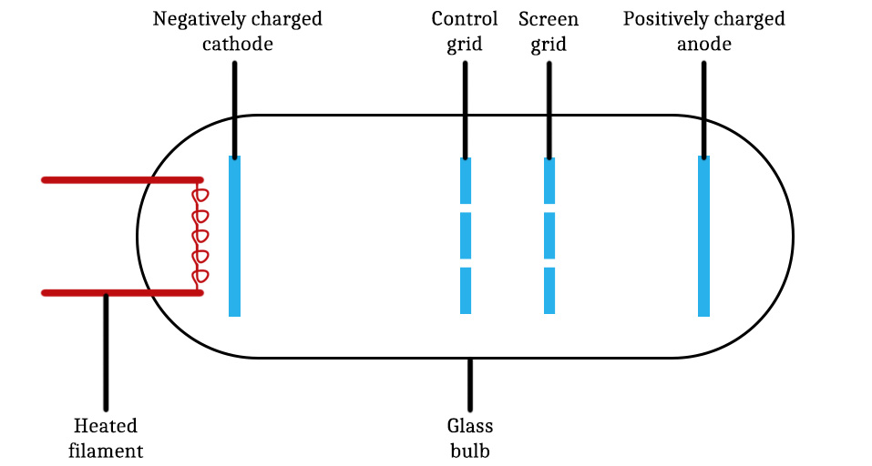
The main drawback of the triode is its tendency to produce signal oscillation due to the capacitance of the grid/anode pair. To remedy this, a screen grid is added between the anode and the control grid. This acts as an electrostatic shield between the two elements, not only solving the problem of signal oscillation, but also enabling the device to operate at a higher frequency. Furthermore, as the screen grid is positively charged, it helps to attract electrons from the cathode, increasing their speed and consequently the gain of the tube.

A new development in tubes: The Pentode
Unfortunately, the tetrode also come with downside. The addition of a screen grid and the resulting acceleration of the electrons certainly increases the gain, but it also leads to an effect known as 'secondary emission'. This is a physical phenomenon that can be summarised as follows: a particle that strikes a surface with sufficient energy will cause new particles to be emitted by the surface. In this case, the accelerated electrons hit the anode so hard that it releases new electrons from the metal it is made of, adding to the total current. This increase in current results in negative resistance over certain voltage ranges.

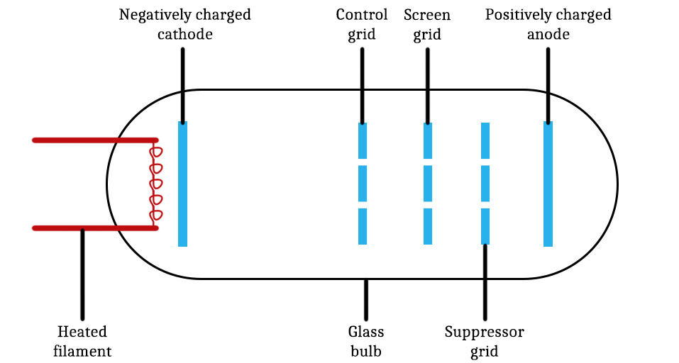
To solve this problem, a new negatively charged grid is added as close as possible to the anode. Its role is to attract and absorb the electrons released by the secondary emission phenomenon, avoiding any negative resistance. This grid is called a suppressor grid and it is this arrangement that is referred as a pentode.
Matched tubes: What are they and when are they relevant?
If you've ever tried to buy power tubes, you'll have noticed that some are sold in sets of two or four, known as matched sets. This means that once the tubes have been manufactured, they are tested and grouped by similar characteristics, ensuring that they operate identically over the same voltage range. Great, but why is that important?
Where this is essential for quality sound reproduction is in the context of a push-pull power amplifier. In this configuration, the positive and negative phases of the signal oscillation are amplified independently. It is essential that each phase of the signal is amplified exactly in the same way, otherwise there is a risk of creating very significant distortion in the final sound.
In other configurations, the use of matched tubes is not mandatory, but the most demanding among us use matched tubes to achieve the most perfect signal symmetry. We invite you to try it out yourself and form your own opinion on the question. To this end, Audiophonics offers a wide range of tubes, matched or not, to meet all your needs.
Power tube data sheet: a glossary of abbreviations
If you get the feeling to look through a tube's datasheet, beyond the graphs describing the tube's behaviour as a function of voltage, you may quickly come across a set of values associated with abbreviations that are often difficult to understand. So here's a glossary of the abbreviations you're most likely to come across.
Certain characteristics may be found under different abbreviations depending on the manufacturer. The different variants we have listed will be separated by a slash (/). If you know the meaning of any abbreviations not listed here, please do not hesitate to contact us.
Cathode-related abbreviations
Uk / Vk : Cathode operating voltages
Ik : Cathode current
Rk : Cathode resistance
Cgk : Grid-cathode capacitance
Cak : Anode-cathode capacitance
Filament-related abbreviations
Uh / Uf / Vh / Vf : Filament heating voltage
Ih / If : Filament heating current
Anode-related abbreviations
Ra /Rp : Anode resistance
Ua / Va : Anode operating voltages (normal)
Ia : Anode current
Wa / Pa : Anode power dissipation
Cga : Grid-anode capacitance
Ri /Rin : At constant control grid voltage, within the anode, the ratio between the variation in current and the resulting variation in voltage.
Grid-related abbreviations
Rg : Control grid resistance
Ug1 /Vg1 : Control voltage grid 1 (control grid)
Ug2 / Vg2 : Grid 2 voltage (screen grid)
Ug3 / Vg3 : Grid 3 voltage (suppressor grid)
μg1-g2 : Amplification factor from grid 1 & 2
Pg2 : Screen grid power dissipation
More general abbreviations
R : Resistance
Gm / S : Transconductance
μ / u : Amplification factor
Pout / W : Output power
Zout : Output impedance
RL : Recommended load impedance
Tbulb : Maximum glass bulb temperature
T : Tube lifetime measured in hours
Rechercher dans le blog
Blog categories
Latest Comments
Audiophonics Team
on DIY Tutorial - PiCorePlayer - Installing...Pierre Bommel
on Lecteur réseau Opensource : SolutionsPierre Bommel
on DIY Tutorial - PiCorePlayer - Installing...Audiophonics Team
on Tutorial DIY - Power cable ELECAUDIO CS-331B


